Mesh Editor
Section I: Bezier Curves and Surfaces
Part 1: Bezier Curves with 1D de Casteljau Subdivision
The de Casteljau algorithm uses a set of connected control points and recursively subdivides
each segment between two consecutive points into two segments of length t and (1-t),
then connects these two newly created points into a new segment, which can then be subdivided
further. After enough recursions, the algorithm defines a single point along the final Bezier curve
at t.
A single step this algorithm in returns a vector of N-1 new 2D points
by calculating a lerp (linear interpolation) between two consecutive points from the input vector of N points.
After a specified number of calls, the function returns
a single Vector2D point. In total, the algorithm should create N choose 2 points before defining the final curve.
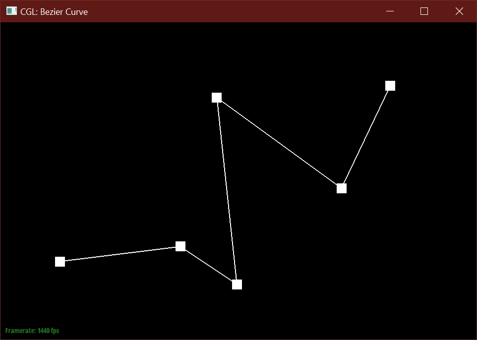
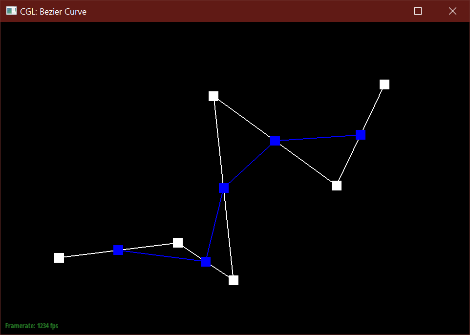
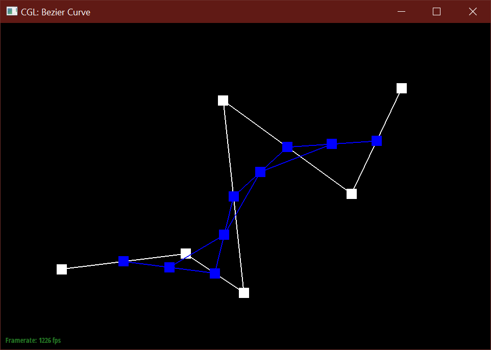
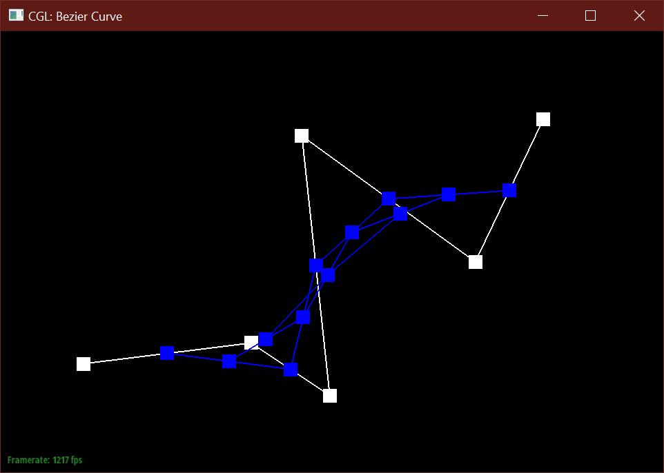
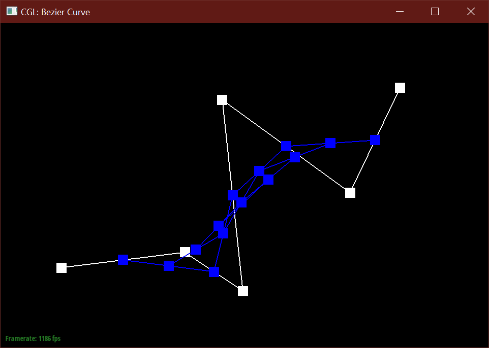
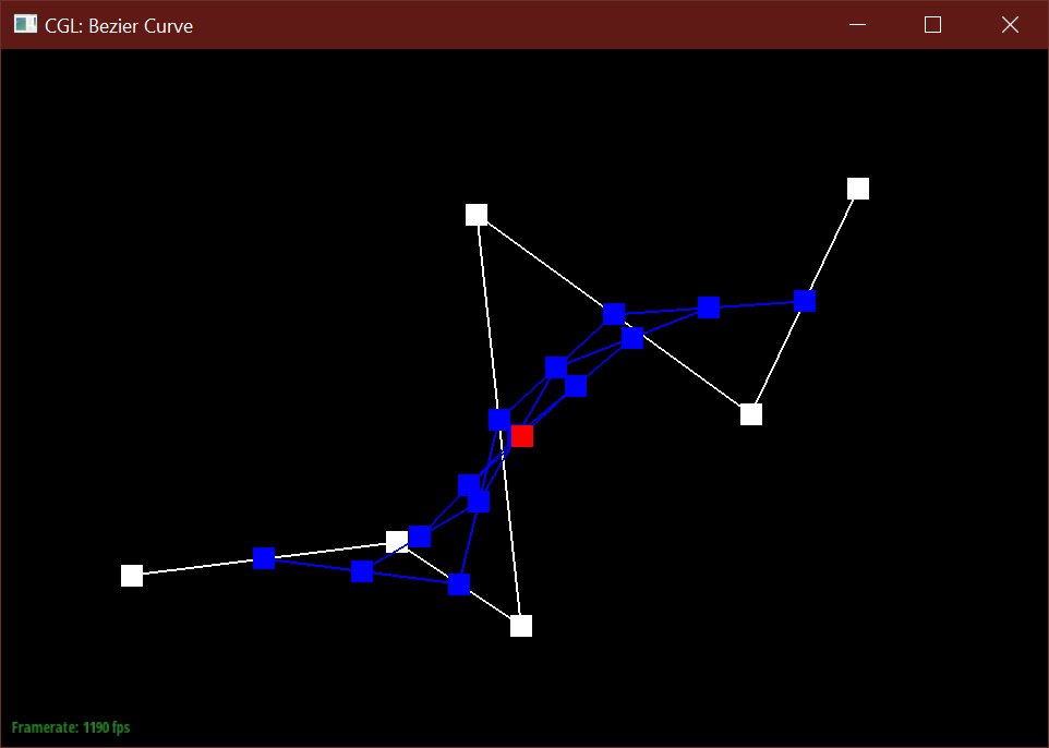
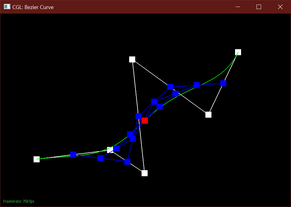
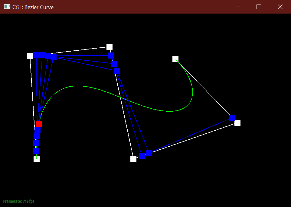
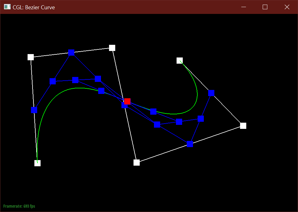
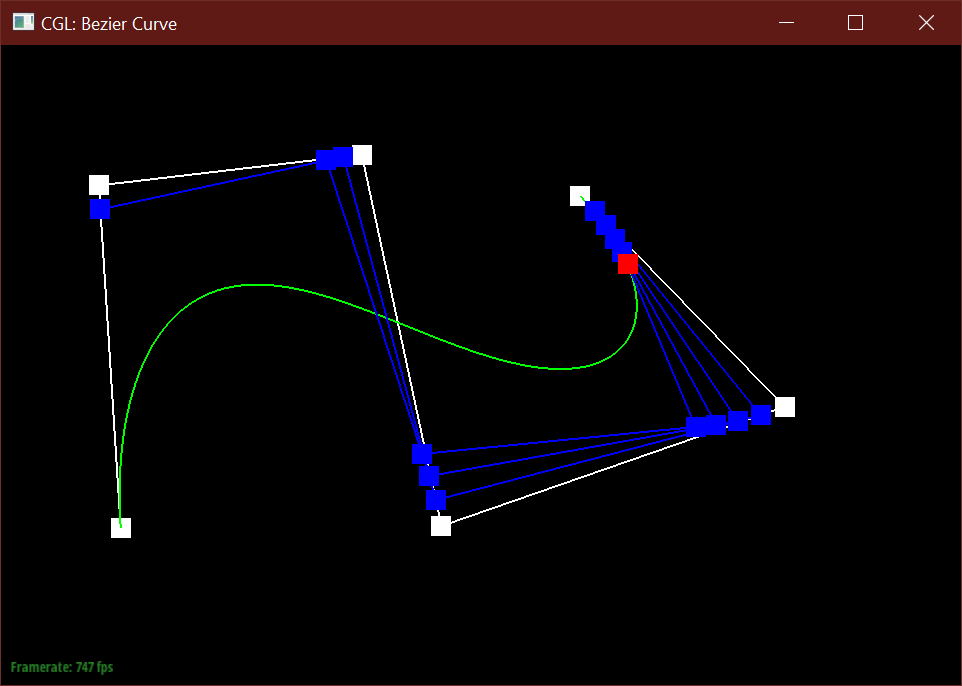
Below is my modified 6 point Bezier curve at a different t values.
Part 2: Bezier Surfaces with Separable 1D de Casteljau Subdivision
de Casteljau extends to Bezier surfaces by defining points in 3D space along two axes,
defined by parameters (u, v) rather than t in the 2D case.
To implement separable 1D de Casteljau, I first extended the idea from part 1 by instead
performing lerps on a vector of consecutive 3D points (rather than 2D), and returning these N-1
3D points, terminating once a single 3D point is found on a curve parameterized by u. These inputs are
rows of m control points parameterized by u. These final points P_i from each row are then inputs
to a final vector parameterized by v.
So then, to find the Bezier curve along the v axis, I performed de Casteljau once againi
on the returned points from each curve at u, and evaluated a Bezier curve for a vector of these points
at the parameter v. The final point returned by this process lies on the Bezier surface at (u, v).
Section II: Sampling
Part 3: Average normals for half-edge meshes
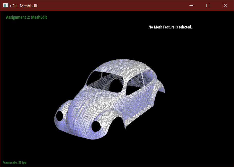
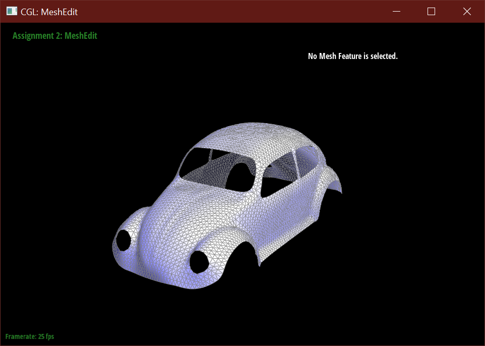
To implement area-weighted normals, I used an intial halfedge to traverse through adjacent faces in the mesh. For each face, if it is not a boundary, then I calculated its area-weighted normal by taking the half of the cross-product of two vectors, and then weighting that area with the face's normal. I then collected each area-weighted normal from each face into a sum, and normalized its value.
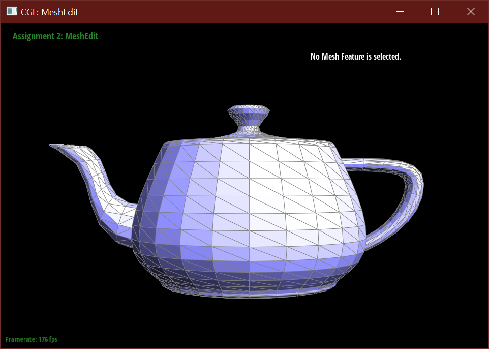
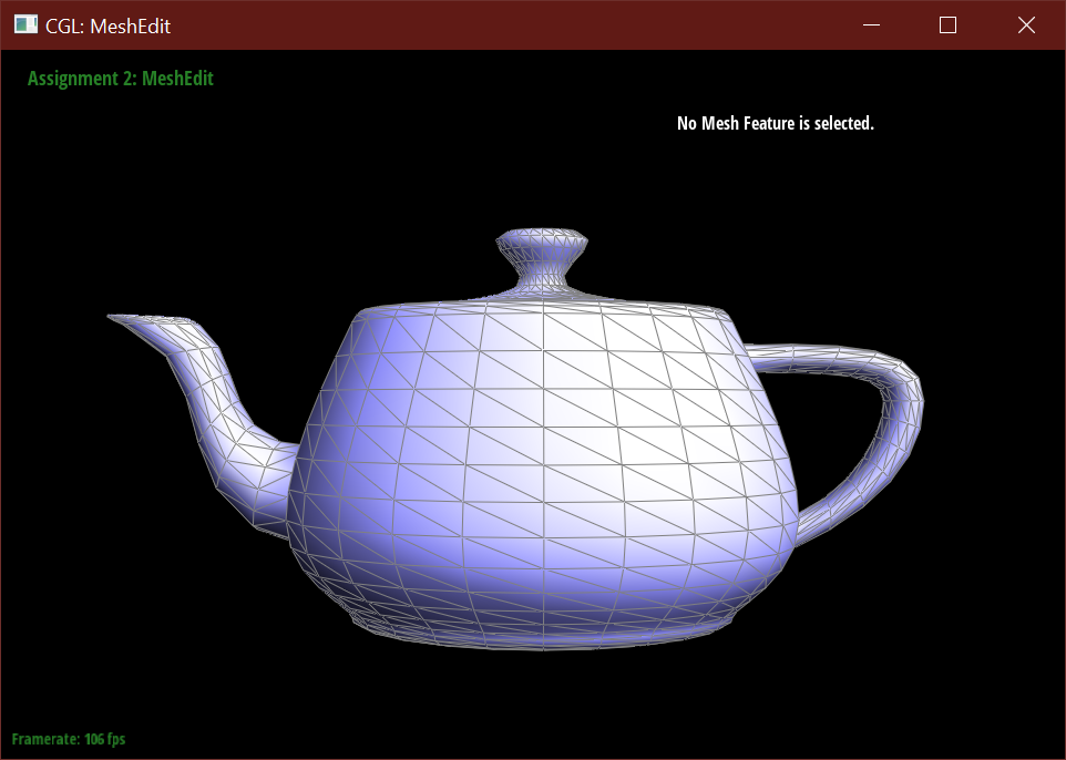
Below is the beetle car model, to demonstrate the calculation on an edge case, a mesh with boundaries.
Part 4: Half-edge flip
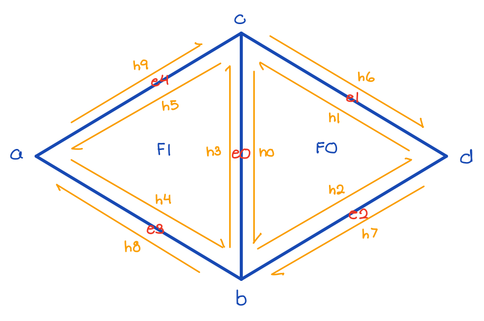
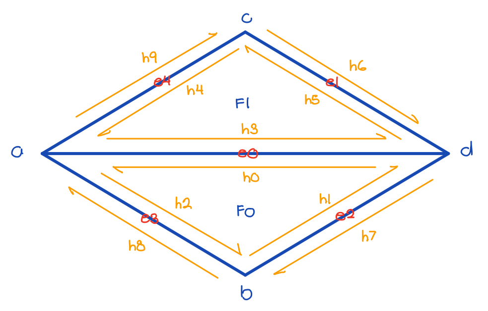
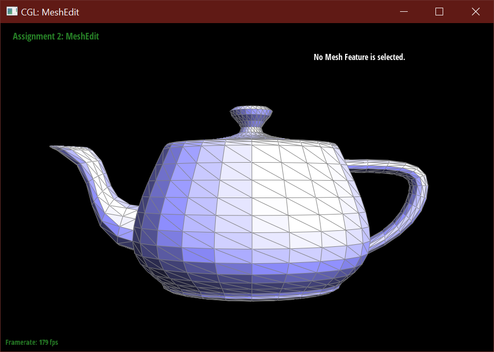
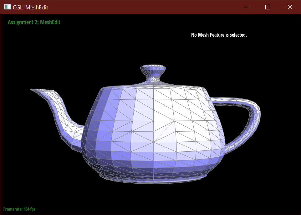
To implement half-edge flips, I followed the below diagram to declare geometric initial elements, including all 10 halfedges, 4 vertices, 5 edges, and 2 faces. Then to perform the flip, I reset the next halfedge, the twin halfedge, the vertex, the edge, and the face that each halfedge neighbors to new pointers that correspond with the flip. If necessary, I also changed some of the pointers for the remaining ertices, edges, and faces.
Part 5: Half-edge split
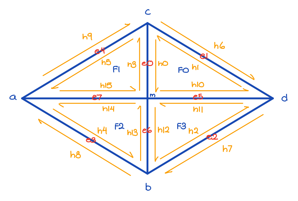
To implement half-edge splits, I followed the below diagram to declare initial geometric elements, including all 10 halfedges, 4 vertices, 5 edges, and 2 faces. Since splitting creates new mesh elements, I allocated space for a new midpoint vertex, 2 faces, 3 edges, and 6 halfedges. Then to perform the split, I reset the next halfedge, the twin halfedge, the vertex, the edge, and the face that each halfedge neighbors to new pointers that correspond with the split. If necessary, I also changed some of the pointers for the remaining ertices, edges, and faces. To reduce some overhead, I retained some existing pointers like the outer edges from before the split.

Part 6: Loop subdivision for mesh upsampling
To implement loop subdivision, I first pre-computed the locations of all new and old vertices that will be
or already are on the mesh. This pre-computation iterates through all edges in the mesh, calculating new vertices
according to the given formula: 3/8 * (A + B) + 1/8 * (C + D), or updating old vertices according to the given formula
(1 - n * u) * original_position + u * original_neighbor_position_sum. I then flagged these edges and vertices appropriately, as
pre-computation does not yet create any new geometry.
The next part of my implementation involves the 4-1 subdivision algorithm and the vertex updates.
This part of my code caused the most errors because of incorrect uses of the isNew flag on the edges
and vertices to determine what edges to flip. To split all original edges, I checked for whether or not
an edge's vertices were both not new, and then after splitting updated the newly created vertex with its
stored position (calculated back in the pre-computation step) and then flagged as new. I then flipped any
new edge that connected an old vertex to a new vertex. Finally, I updated any old vertices with their
stored new positions.
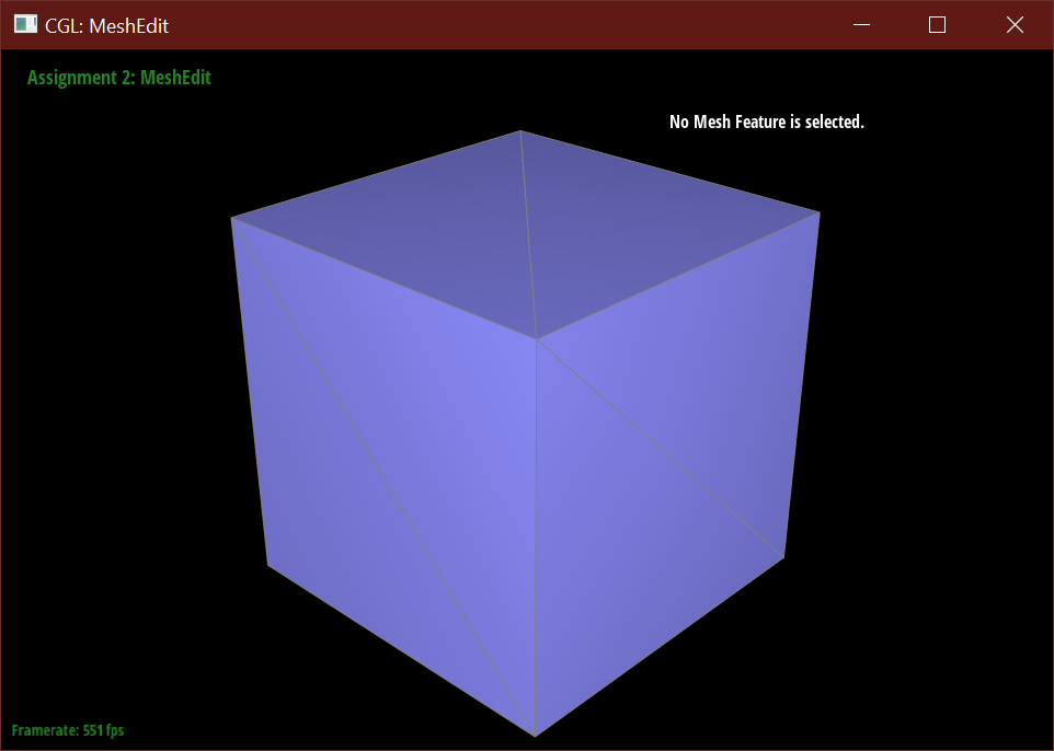
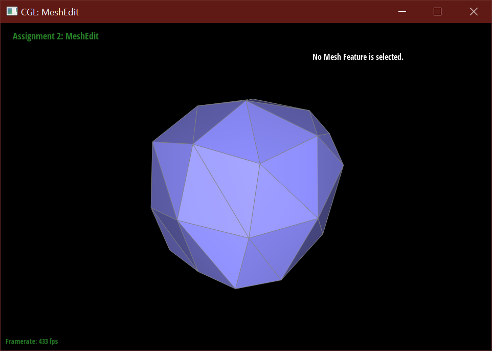
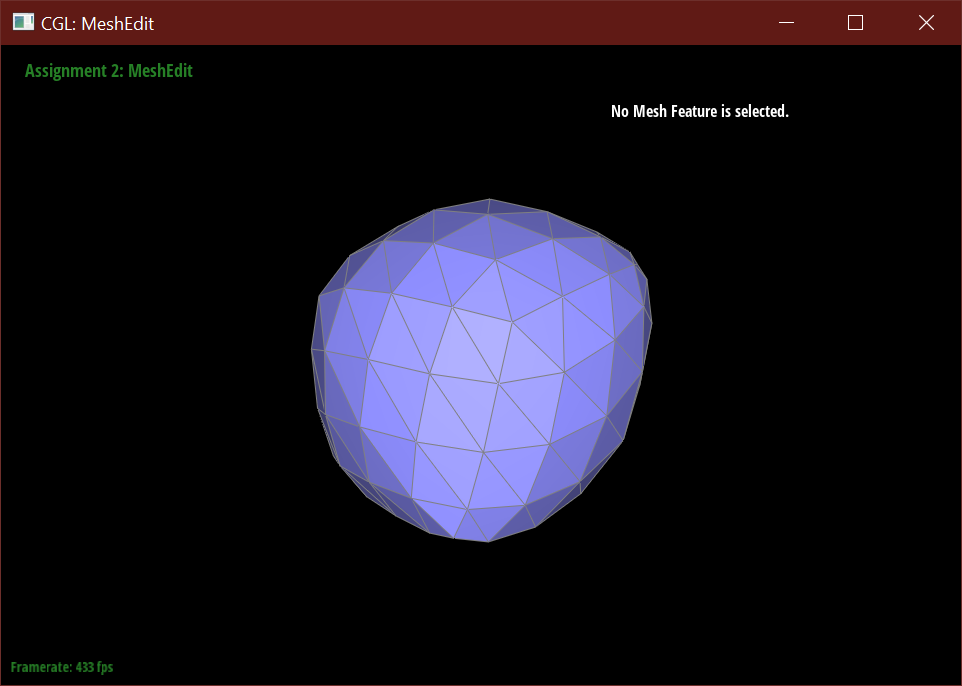
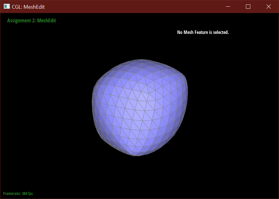
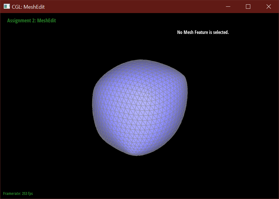
After loop subdivision, sharp corners (especially on the cube) become rounded and edges are smoothed out. This rounding effect can be reduced with some pre-splitting of a face. Subdivision smoothing has a weaker effect on tightly placed edges.
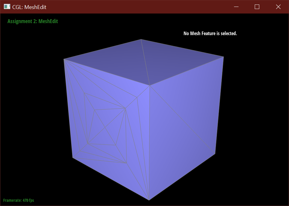
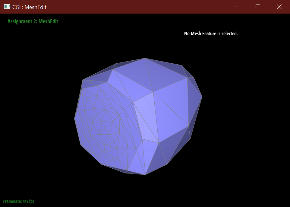
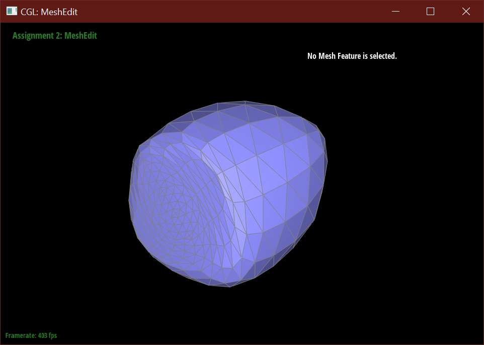
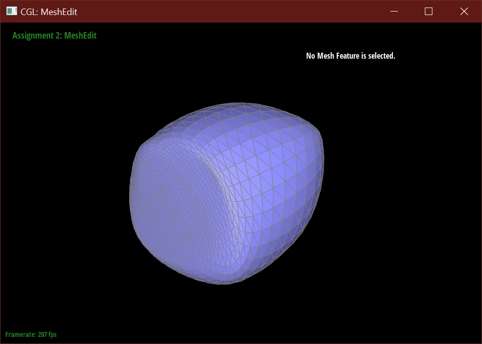
When subdividing without pre-processing, the cube using the initial mesh is warped and pinched at two of the corners.
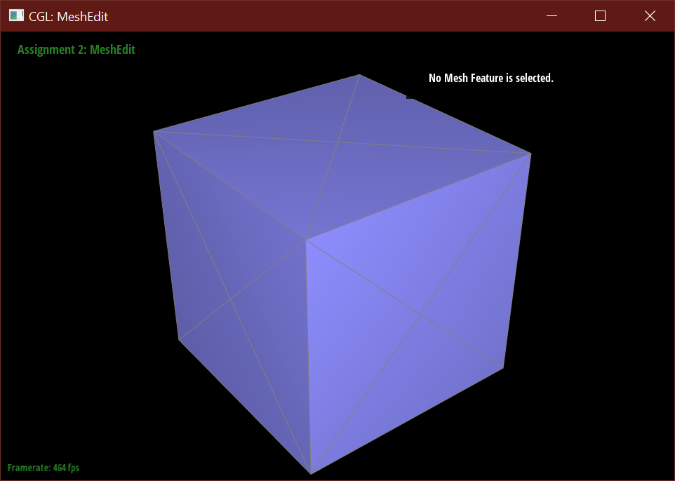
It's possible to make the subdivision more symmetric by pre-processing the face edges.
This alleviates the problem with asymmetry because the subdivision algorithm will create a symmetric number
of new faces on each side when the initial geometry is symmetric. In the original mesh, the diagonal sides
resulted in pinching where corners meet because the subdivision algorithm could not evenly smooth the particular
set of edges that connect at corners of the cube.
After splitting each face, the mesh then subdivides nicely into a rounded dice shape.
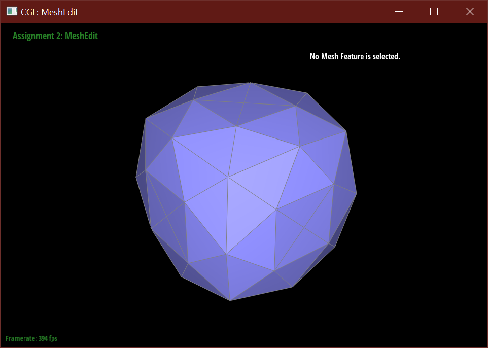
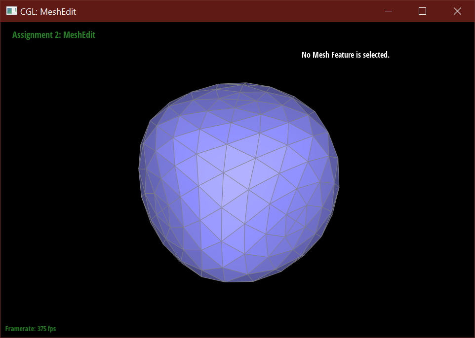
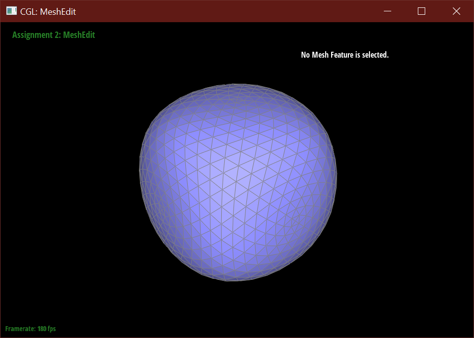
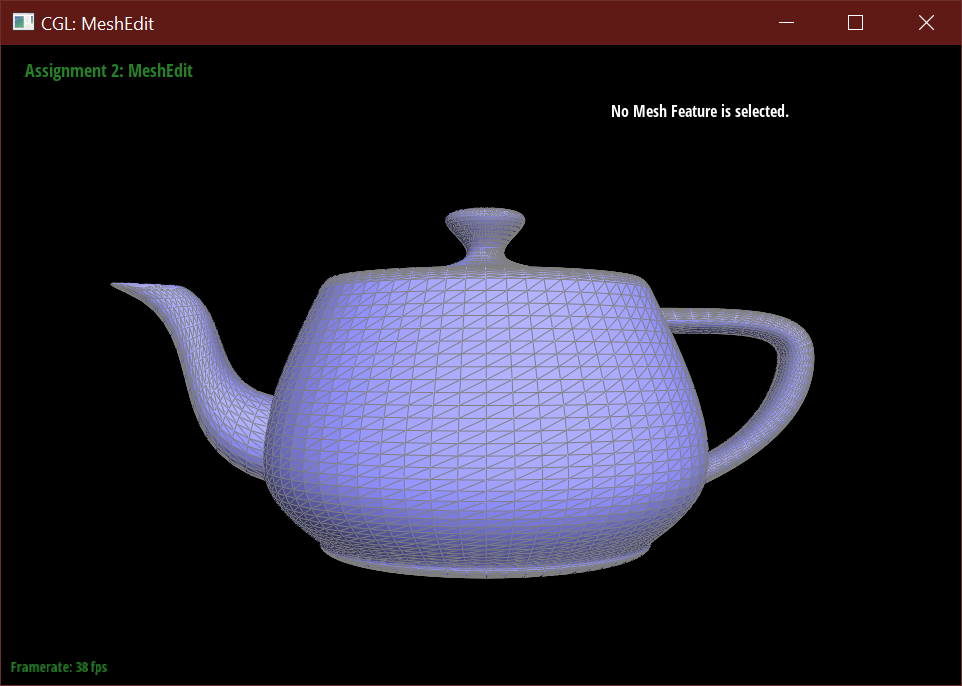
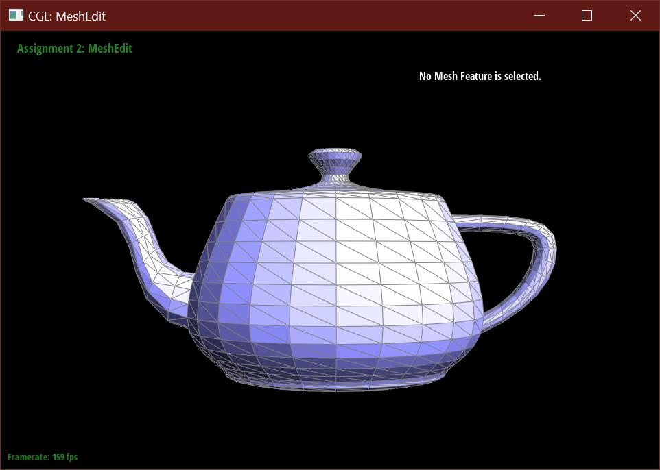
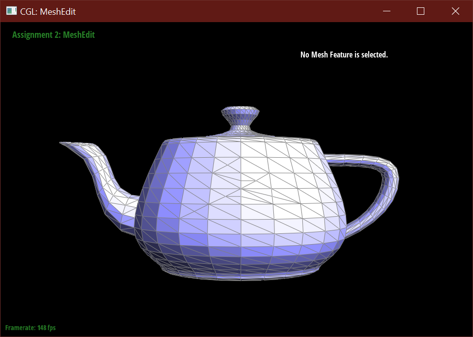
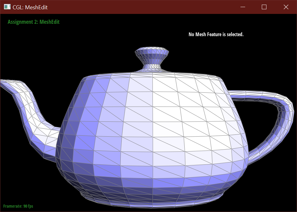
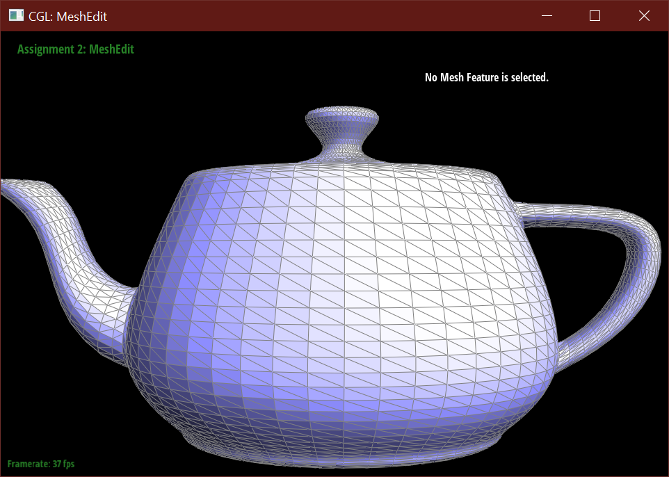
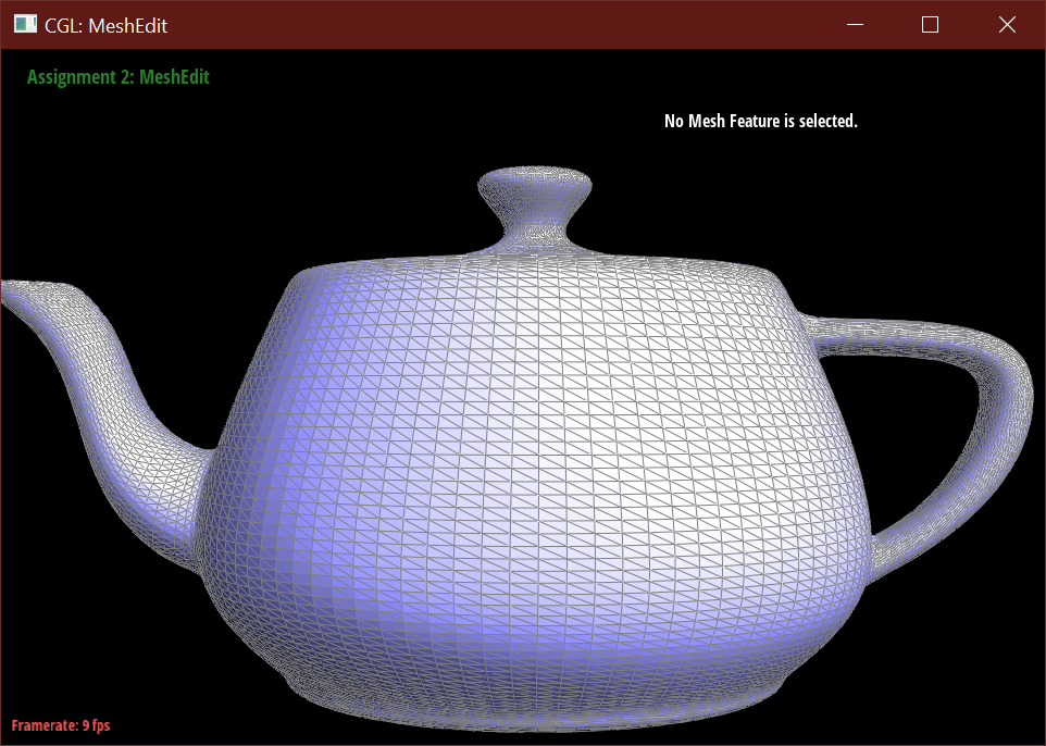
Below demonstrates the subdivision algorithm on the teapot mesh.
Bugs Encountered
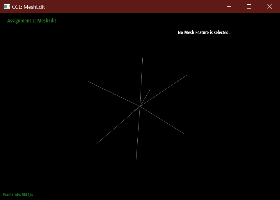
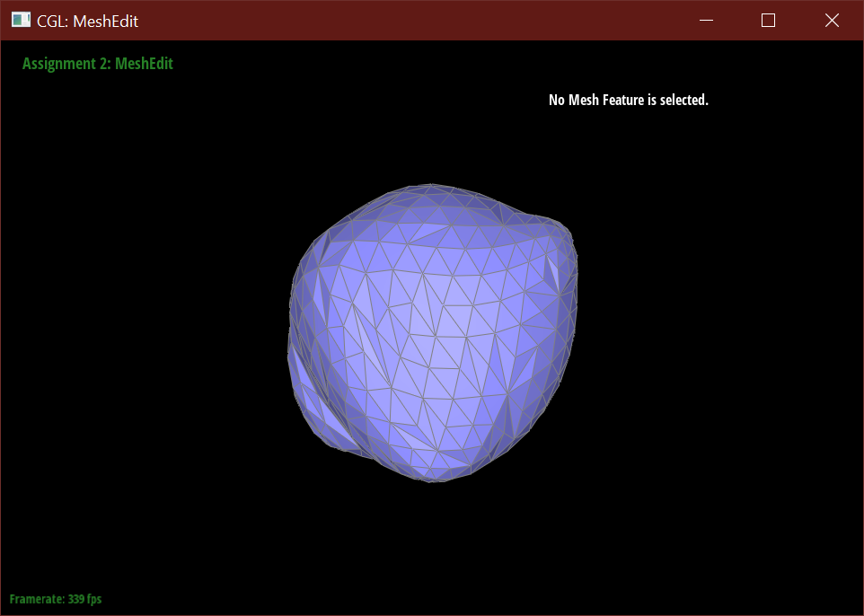
- Updating the positions of new vertices after splitting and flipping resulted in the mesh imploding into only edges connected to one central vertex.
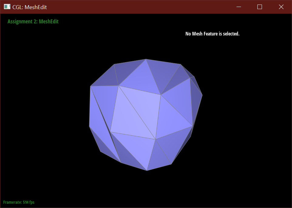
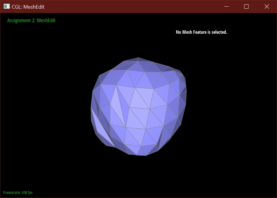
- When I only checked if the immediate vertex is new and its neighboring vertex is old before flipping, rather than also accounting for the reverse, resulted in this warped cube.
Section III: Mesh Competition
Design your own mesh!
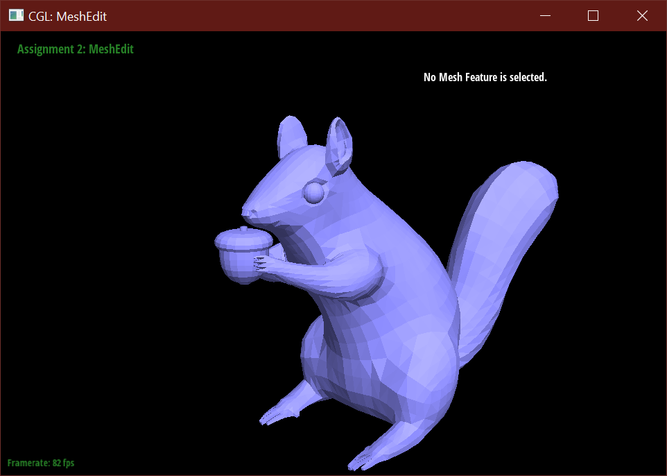
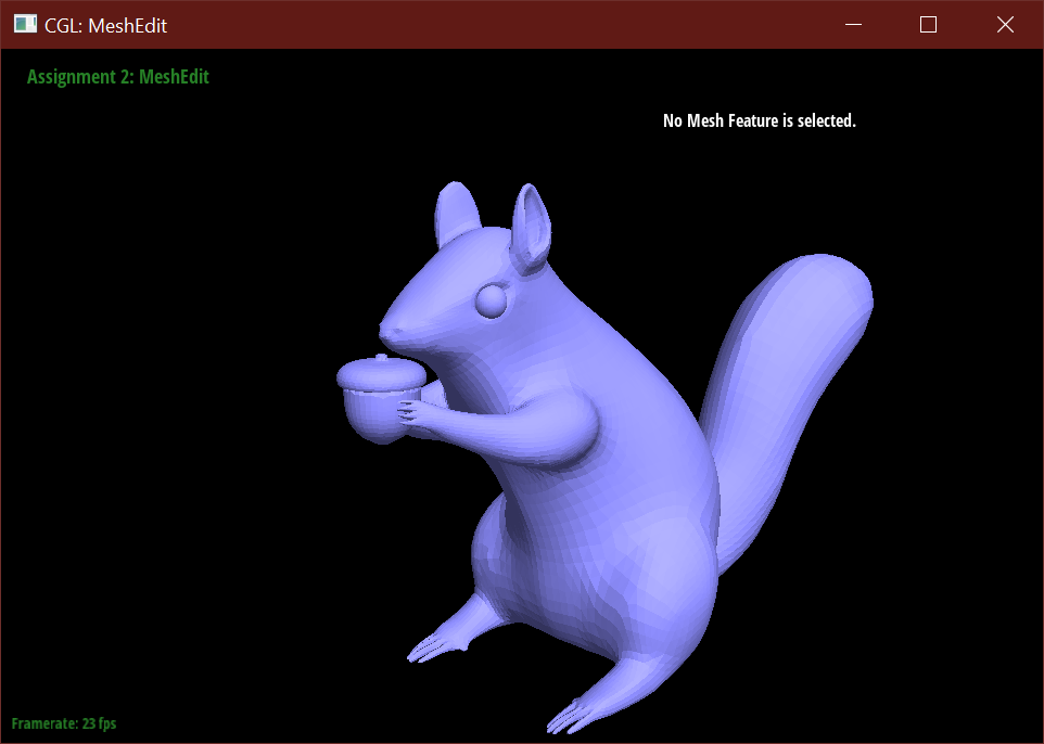
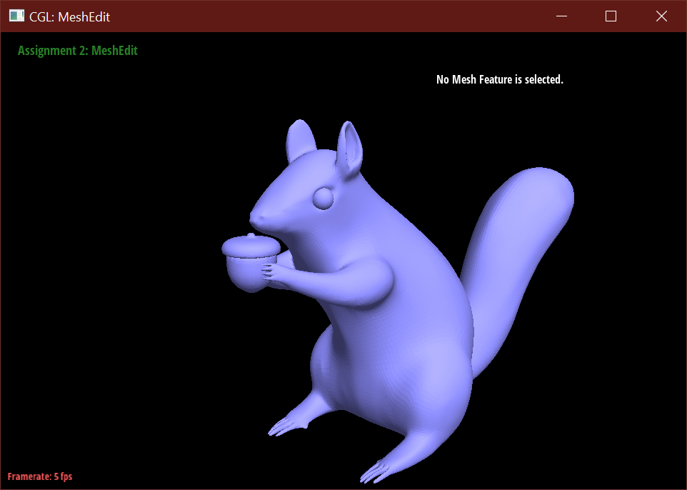
Beyond the simple humanoid mesh, I used reference images of squirrels and box modeled from
a plane traced along these several reference images. This squirrel was modeled in
Autodesk Maya.
This entry won second place.